Victron Energy
Victron BMS 12/200 Battery Management System
Victron BMS 12/200 Battery Management System
Couldn't load pickup availability
SKU:BMS012201000
Victron BMS 12/200 Part Number: BMS012201000
Victron Battery Management System BMS 12/200
Why a Battery Management System (BMS) is needed:
1. A LFP cell will be damaged if the voltage over the cell falls to less than 2.5V.
2. A LFP cell will be damaged if the voltage over the cell increases to more than 4.2V. Lead-acid batteries will eventually also be damaged when discharged too deeply or overcharged, but not immediately. A lead-acid battery will recover from total discharge even after it has been left in discharged state during days or weeks (depending on battery type and brand).
3. The cells of a LFP battery do not auto-balance at the end of the charge cycle. The cells in a battery are not 100% identical. Therefore, when cycled, some cells will be fully charged or discharged earlier than others. The differences will increase if the cells are not balanced/equalized from time to time. In a lead-acid battery a small current will continue to flow even after one or more cells are fully charged (the main effect of this current is decomposition of water into hydrogen and oxygen). This current helps to fully charge other cells that are lagging behind, thus equalizing the charge state of all cells. The current which flows through a fully charged LFP cell however, is nearly zero, and lagging cells will therefore not be fully charged. Over time the differences between cells may become so extreme that, even though theoverall battery voltage is within limits, some cells will be destroyed due to over or under voltage.
A LFP battery therefore must be protected by a BMS that actively balances the individual cells and prevents under and over voltage.
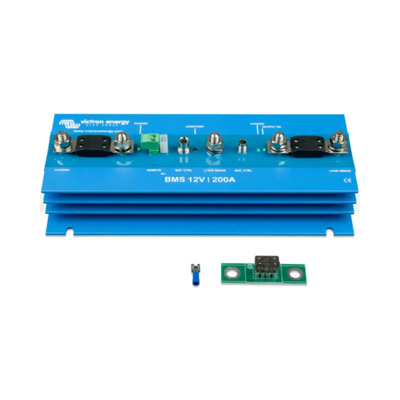
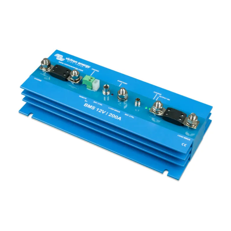
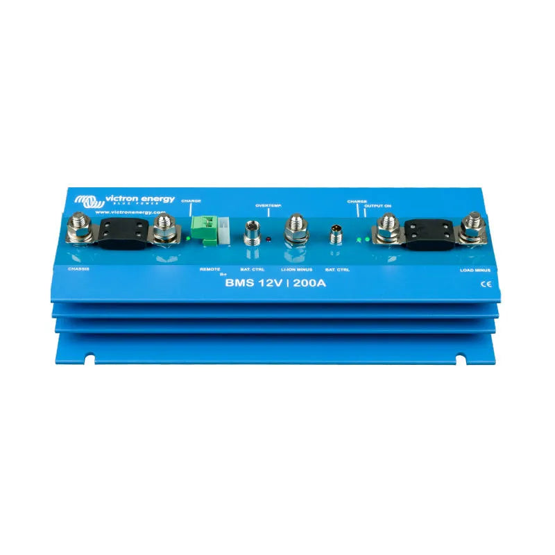
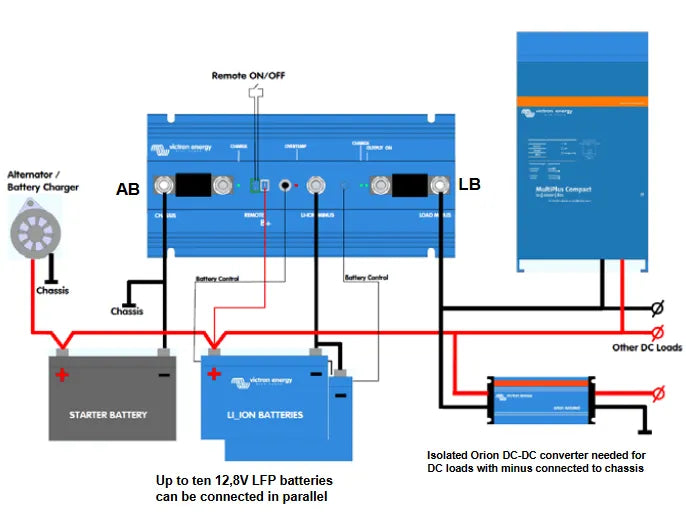
BMS 12/200 protects the alternator (and wiring), and supplies up to 200A in any DC load (including inverters and inverter/chargers)
1. Mount the BMS preferably on a vertical surface, for optimal cooling.
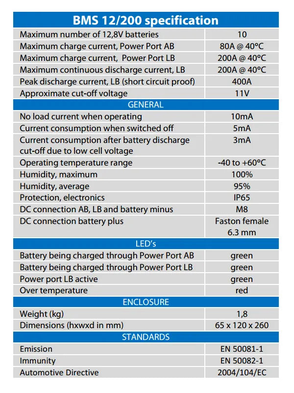
2. Determine the rating of fuse AB (see figure and table 1) The fuse on input AB doubles as a shunt. The BMS will limit the input current according to the rating of this fuse. For fuse and corresponding current limit. Choosing the right fuse will prevent overheating of the alternator and/or DC cabling.
3. Determine the rating of fuse LB (see figure). This fuse should be rated in accordance with the expected load
current and the cross section of the cabling to the load.
4. Disconnect the cabling from the plus pole of the starter battery.
5. Pull off the REMOTE on/off connector to prevent unwanted switching of the BMS.
6. Install and connect all electrical cabling and fuses AB,leave the plus poles of the Li-ion batteries and starter Battery disconnected.
7. Daisy-chain the battery control cables between the and connect to the BMS.
8. Connect the plus cabling to the Li-ion batteries and battery.
9. Reinsert the REMOTE on/off connector on the BMS. The BMS is now ready for use.
Notes:
a) A battery charger can be connected to input AB instead of the alternator.
b) The Li-ion batteries can be charged as well as discharged through input/output LB.
Share